Assembly of Feedthru Kits
The 2 and 4 post feedthrus were developed to be used in more traditional electronic bays. They provide a reliable electrical connection that can be field repaired easily.
Both sizes are assembled in the same fashion, so only the 4 Post Feedthru assembly is detailed. There is a picture of a completed 2 Post Feedthru Assembly at the end of this page.
Note: It is not possible to install the feedthru once you have assembled it completely. You can install the feedthru first in your electronics bay and then assemble the feedthru in place with the instructions or you can assemble it and then remove the wire and hardware off the one side when you are ready to install (the hex spacers are a press fit when installed, so they will stay with the feedthru and not affect installation) to install the feedthru.
What you need for this
- Two or four 18-22 AWG prepared wires with #6 crimp terminals - Preparation Guide for Crimp Terminals
- 2 or 4 Post Feedthru
- Hardware from kit
- two/four 1/2 inch long 6-32 aluminum hex spacers
- two/four 1" 6-32 machine screws
- two/four 3/16" 6-32 machine screws
- two/four #6 flat washers
- four/eight #6 internal lock washers
- 20-30 watt soldering iron
- rosin core solder
- heat gun
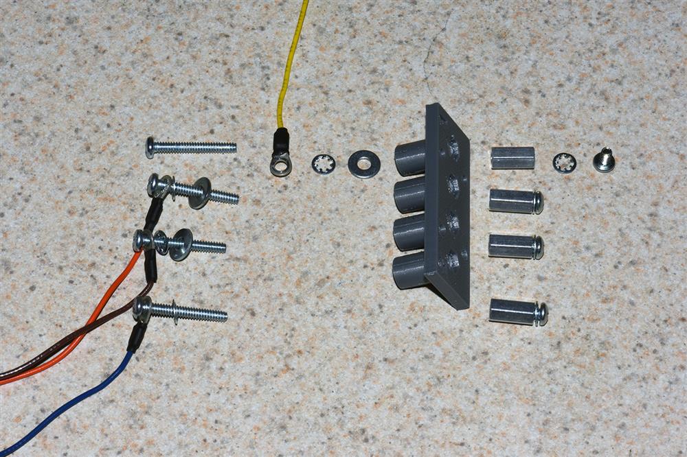
Step 1 - Layout parts required for assembly. Put a crimp terminal, internal lock washer, & flat washer on each 1" screw. Put an internal lock washer on each 3/16" screw. At this point you can install the feedthru in your electronics bay and continue to step 2
Step 2 - Insert crimp terminal screws into feedthru, start the thread on the spacer and tighten (make sure hex base of spacer goes into well on feedthru).
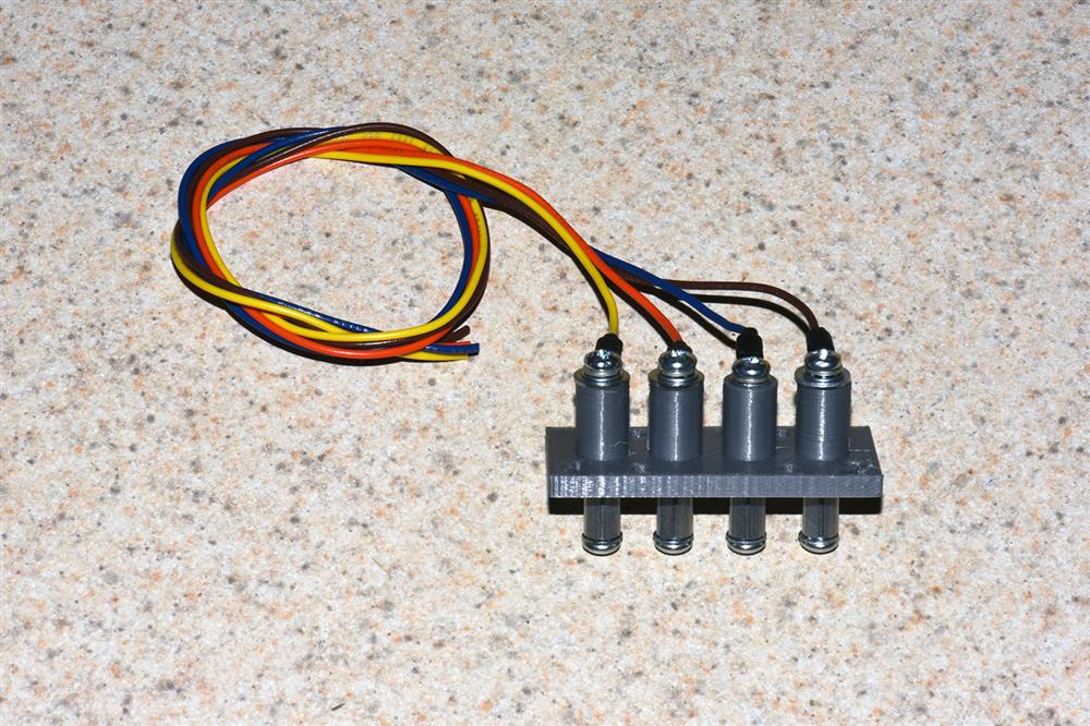
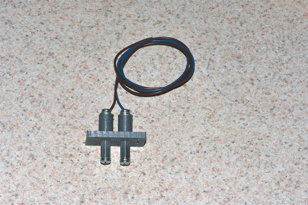
This completes the 4 Post Feedthru Assembly
Completed 2 Post Assembly