Assembly of Deploy Kits
The 2 and 4 post deploy kits were developed to be used in single, dual, and redundant dual deployment bays and come in both coupler tube (CT) and end cap mounting (motor retainer). They can also be used to connect any circuit to a point outside the bay. They provide a reliable electrical connection and when assembled without epoxy, can be repaired or replaced for different bay configurations.
There are two different styles of deploy parts and both of them are held in place by three 4-40 machine screws that go through and attach to a fixed deploy ring. The first style fits inside of a coupler tube (CT) and comes in both a two post and four post version. The second style is an end cap that mimics an aft motor closure, so a motor retainer can be used to hold the bay in place. The end cap style also comes in a two or four post version.
Both versions are assembled in the same fashion, so only the 4 Post versions are shown in the photos.
Note: the assembly instructions here are strictly informational and do not take into account where the wires are coming from for the deployment posts. Normally, the deploy kits would be the last thing to install and the wires would actually be coming out the bay ends from other bay parts. This does not mean you can't pull the wires in and attach them to other bay parts, but this might be the more difficult way to do it. Please take a big picture view of your final assembly into mind.
End Cap Style Deploy Assembly
What you need for this
- Two or four prepared #6 crimp terminals - Preparation Guide for Crimp Terminals
- 2 or 4 Post End Cap Deploy part
- Hardware from kit
- one/three 1/2 inch long 6-32 aluminum hex spacers
- one 3/4" long 6-32 aluminum hex spacer
- two/four 7/8" 6-32 machine screws
- two/four 3/16" 6-32 machine screws
- two/four #6 flat washers
- four/eight #6 internal lock washers
- two/four 18-22 AWG wires from connector kit
- one tie wrap
- phillips screwdriver
- wire cutters
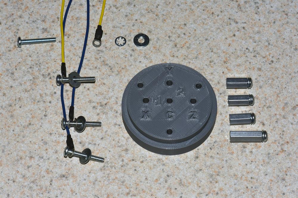
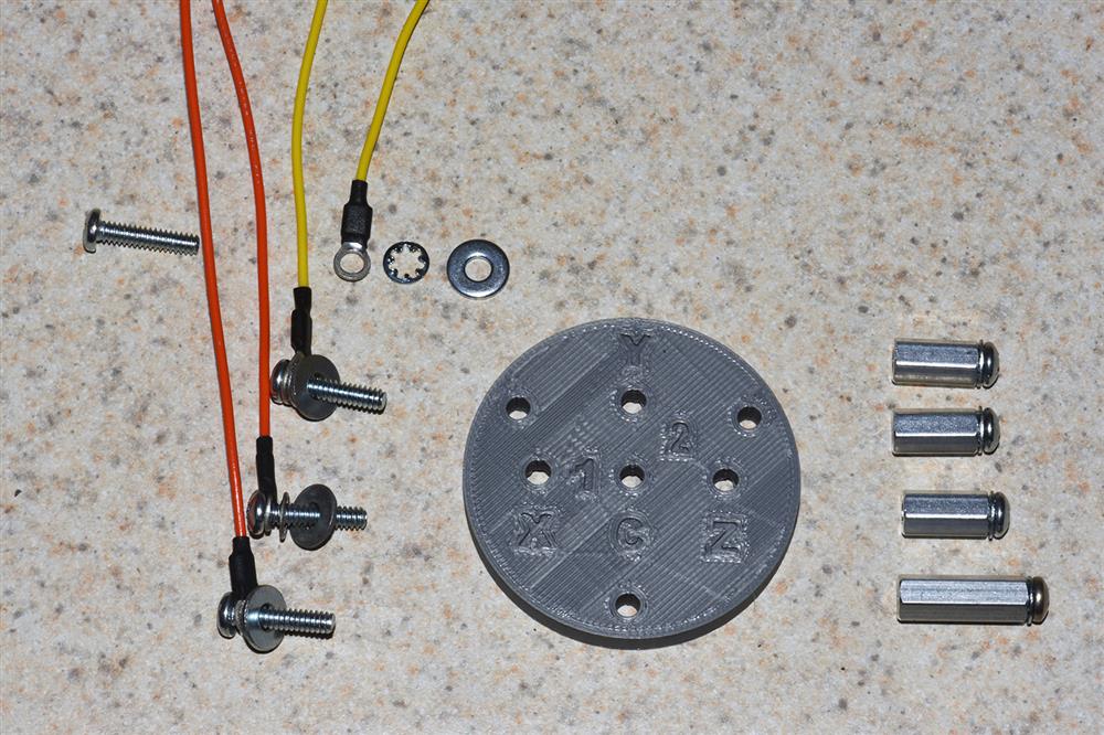
Step 1 - Layout parts for assembly. Put a crimp terminal, an internal lock washer, & a flat washer on each 7/8" screw. Put an internal lock washer on each 3/16" screw and install them on each spacer.
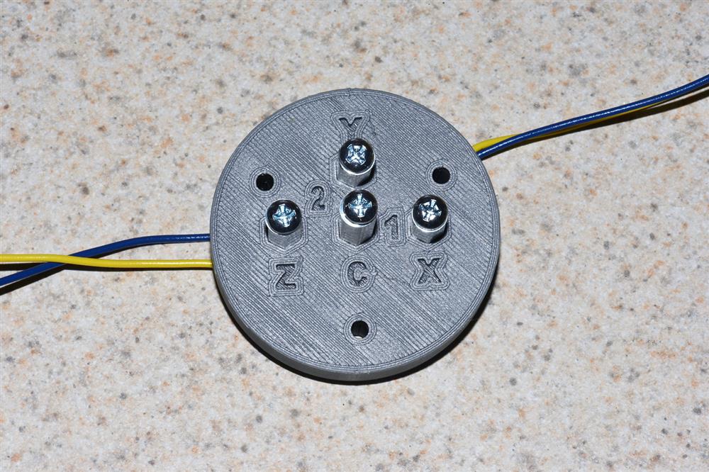
Step 2 - Insert crimp terminal screws into part, start the thread on the spacer and tighten (make sure hex base of spacer goes into well on part). Arrange wires as shown.
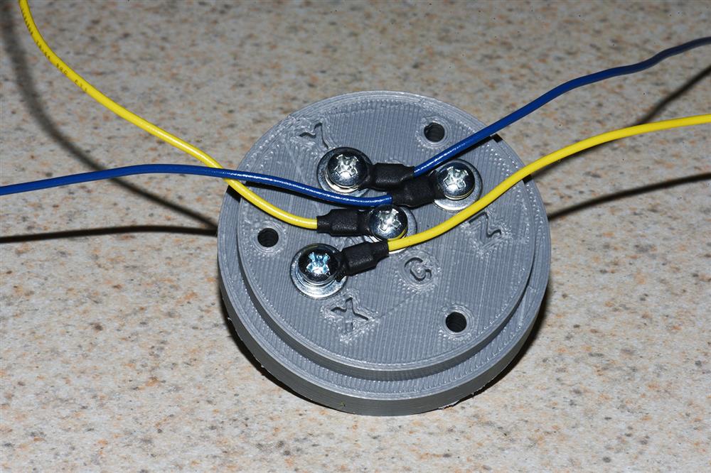
Step 3 - Using a small flat blade screwdriver underneath each terminal, bend up the wire terminals as shown.
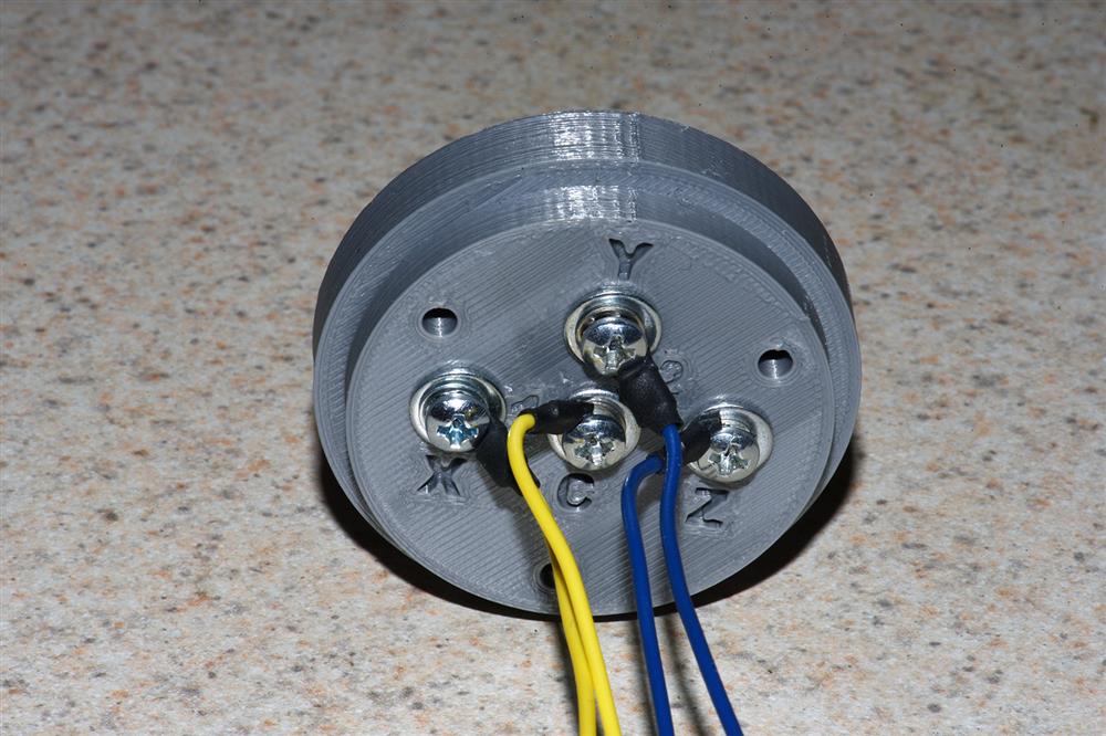
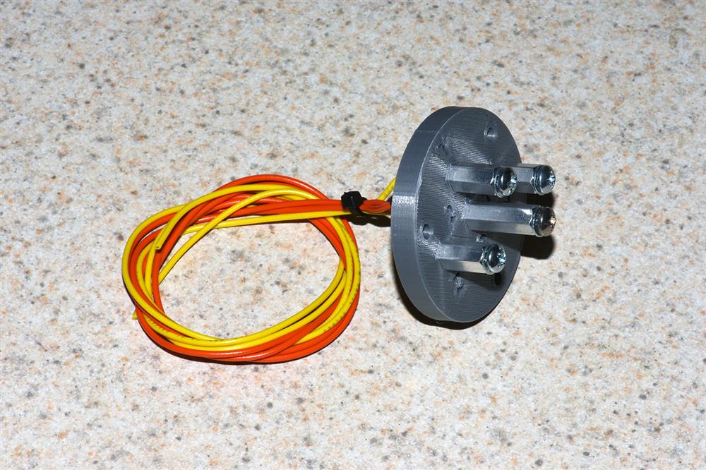
Step 4 - use a tie wrap and group the wires in the back
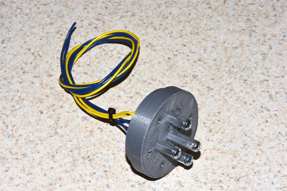
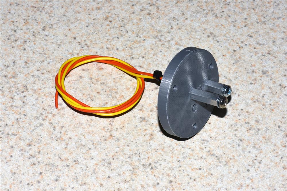
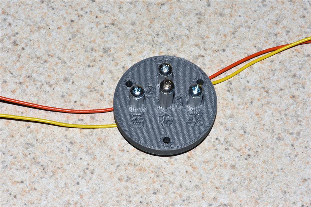
Completed 2 Post End Cap Deploy Assembly
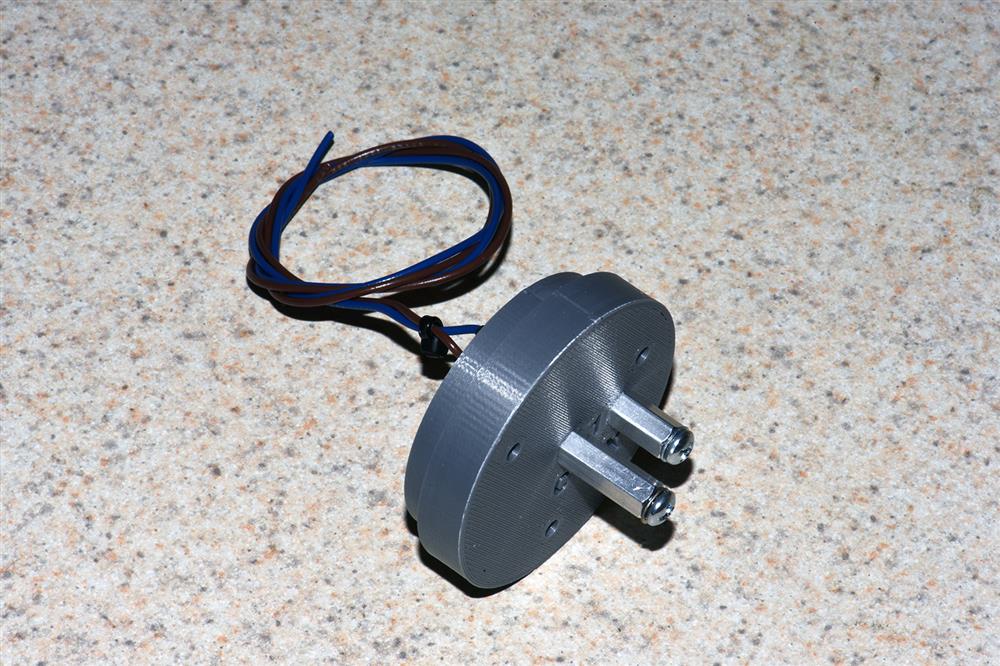
This completes the 2/4 Post End Cap Deploy Assembly
Coupler Tube 2/4 Post Deploy Assembly
What you need for this
- Two or four prepared #6 crimp terminals - Preparation Guide for Crimp Terminals
- 2 or 4 Post CT Deploy part
- Hardware from kit
- one/three 1/2 inch long 6-32 aluminum hex spacers
- one 3/4" long 6-32 aluminum hex spacer
- two/four 5/8" 6-32 machine screws
- two/four 3/16" 6-32 machine screws
- two/four #6 flat washers
- four/eight #6 internal lock washers
- two/four 18-22 AWG wires from connector kit
- one tie wrap
- phillips screwdriver
- wire cutters
Step 1 - Layout parts for assembly. Put a crimp terminal, an internal lock washer, & a flat washer on each 7/8" screw. Put an internal lock washer on each 3/16" screw and install them on each spacer.
Step 2 - Insert crimp terminal screws into part, start the thread on the spacer and tighten (make sure hex base of spacer goes into well on part). Arrange wires as shown.
Step 3 - Using a small flat blade screwdriver underneath each terminal, bend up the wire terminals as shown.
Step 4 - use a tie wrap and group the wires in the back
Completed 2 Post CT Deploy Assembly